In my professional pursuits this year, I began using the Ignition platform from Inductive Automation, a Supervisory Control and Data Acquisition (SCADA) system widely used in industrial applications. In learning how to configure and extend Ignition, I was delighted to find that Inductive Automation provides a free Maker Edition, to allow makers and students to use Ignition for non-commercial experimentation. Not only that, but they also provide a Docker image of Maker Edition for a quick and simple starting point!
I installed the Docker image of Maker Edition on a Raspberry Pi at home, instantly creating a home lab for experimenting with IoT device communication and data. In addition to these software resources, the maker of Ignition provides a comprehensive amount of online training on their Inductive University web site. As a grizzled and sometimes jaded software professional, it takes a lot these days for a software company to impress me. I have to say, however, that Inductive Automation has done just that with Ignition. It has been a pleasure to learn and use for the past few months.
In addition to learning to configure and use the Ignition SCADA platform, I have learned several other related concepts and technologies regarding Internet of Things (IoT) device communication. One of these other technologies is the Modbus protocol, the de facto communication standard for industrial devices. This blog posts shows how to get started with Modbus and Ignition with a fun example application. Keep reading if you find yourself wanting to learn more about the IoT beyond commercial off-the-shelf home automation devices and closer to the hardware with Modbus communication and industrial-grade data acquisition software.
Ignition Maker Edition and Simulated Devices
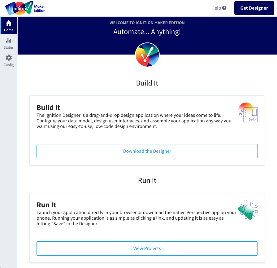
When you first run Ignition Maker Edition, you can navigate to the Ignition Gateway’s home page as the starting point for adding device connections.
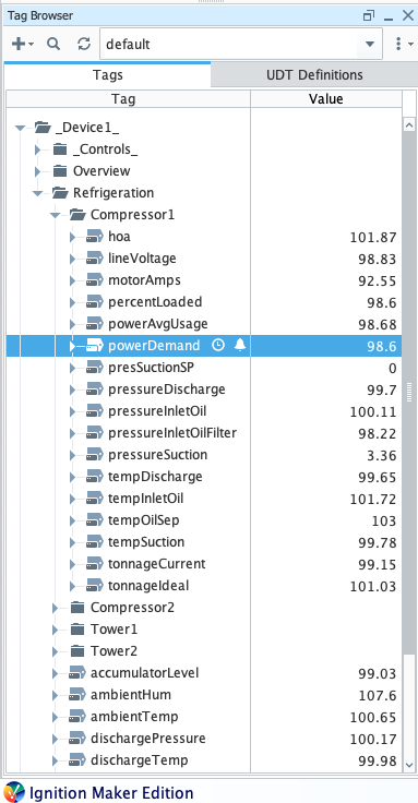
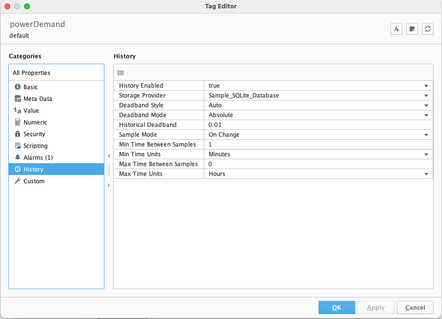
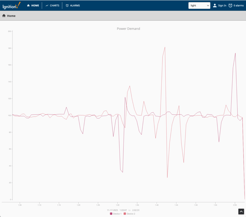
If you’re like me, you probably don’t have very many (or indeed any) industrial devices laying around your house. Fortunately Ignition provides a “Programmable Device Simulator” option when adding an OPC UA Device Connection. As you can see below, when you add a simulated device you have the option of creating many simulated data tags from industrial applications such as refrigeration equipment. I was interested in monitoring device data over time, so I configured this “powerDemand” tag for Compressor 1 to store values every minute in the Historian database.
After adding two of these simulated compressors, I was able to plot the history of their Power Demand values that were now being tracked over time.
Solid Metal
Simulating devices provides a great jump start in learning Ignition, but I wanted to acquire data from a REAL device. Looking around, I saw just the perfect thing. If you’ve ready any of my blog posts and are aware of my obsession, you probably know what I had in mind…
LET’S CONNECT A COMMODORE 64 TO IGNITION!!!
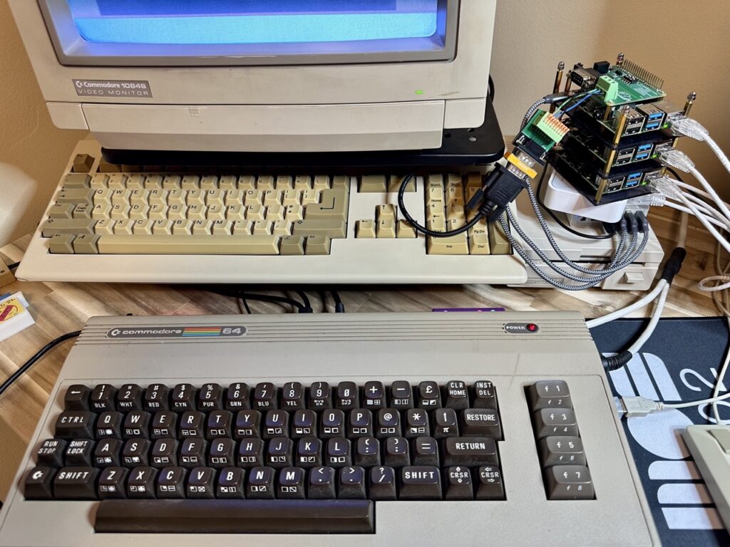
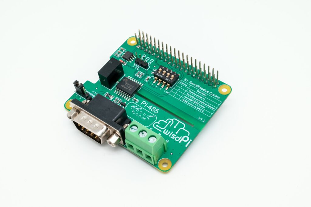
A Commodore 64 doesn’t have a TCP/IP networking stack, but it can communicate using the standard RS-232 serial communication protocol. To enable serial communications capabilities on my Raspberry Pi, I ordered a Pi-485 Raspberry Pi HAT. This HAT would not only provide serial communication capabilities but give me the option to connect to devices that support the RS-485 protocol in the future. (RS-485 is a serial communication standard widely used by industrial and home automation devices.)
This blog post is not going to dive into the RS-485 protocol. It remains dark magic for me, a protocol that allows multiple devices to communicate without interference across only two wires! Chaining a bunch of devices along just two wires intrigues me, but we will leave that study for another day.
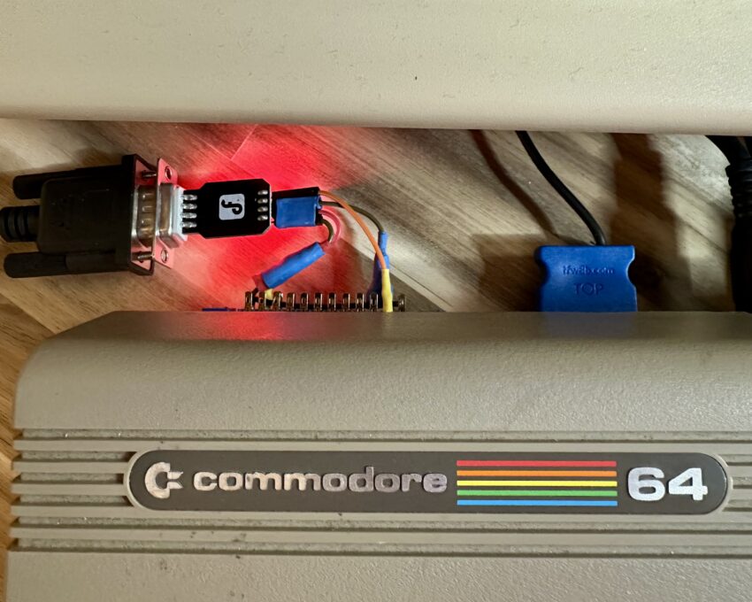
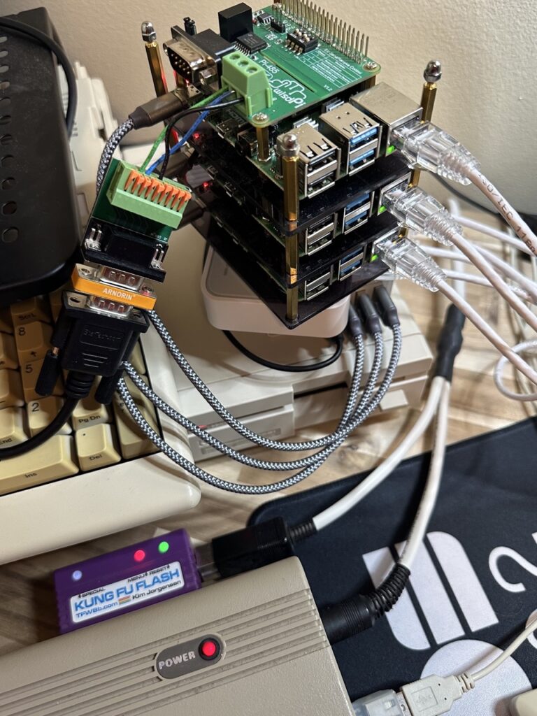
For this experiment, you can see in the image below that I connected the standard DB-9 serial cable to the Pi-485’s terminal block connector. This wasn’t strictly necessary but it helped me to clearly understand and change the connections between the Pi-485’s pins and the standard RS-232 DB-9 pins.
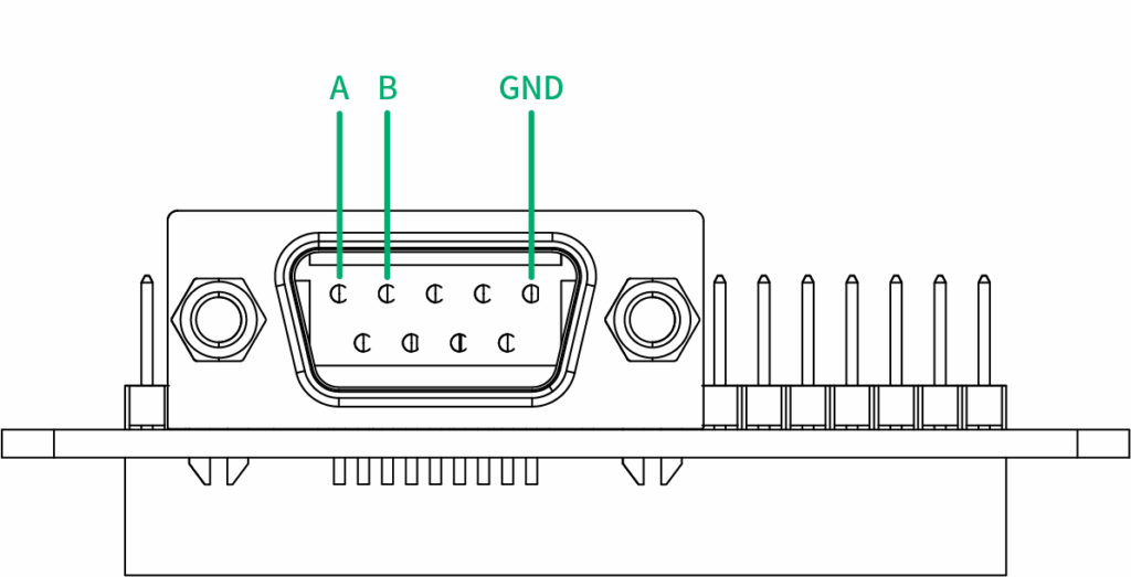
The Pi-485 uses pins 1 and 2 for communication, whereas the standard RS-232 connector uses pins 2 and 3. Given this differences, you can either choose to use a straight connector and have pin 2 on the RS-232 connector (receive data) connect to pin 2 (RS485-B) on the Pi-485, or by using a “null modem” (crossover) adapter, you can switch pin 3 (transmit data) on the RS-232 connector to connect to pin 2 (RS485-B) on the Pi-485. In both cases, pin 1 (RS485-A) on the Pi-485 remains unconnected.
Pi-485:
1 - RS485-A
2 - RS485-B
5 - Ground (GND)
RS-232:
2 - Receive Data (RXD)
3 - Transmit Data (TXD)
5 - Ground (GND)
By using the terminal block on the Pi-485, however, you can connect both pins 2 and 3 on the RS-232 connector to pins A and B on the RS-485 side. By connecting in this way on the terminal block, however, I still could not get the Pi-485 to perform two-way communication. This remains an unsolved mystery (for me) as of this writing. I had to settle with connecting it in either “receive” or “transmit” mode. Either would work, just not both at the same time. For receiving data from the Commodore 64, I obviously connected it in “receive” mode, and that worked just fine.
I mention this failure to accomplish two-way communication using the Pi-485 to help others avoid thinking they did something “wrong” in their serial connection if they don’t immediately see two-way communication. It is just a bit more complicated then using a normal RS-232 communication device on the Raspberry Pi such as a USB dongle.
Testing Serial Communication
Setup and Testing
As a brief aside, it’s always a good idea to test and verify serial communication in a terminal program before jumping into any automated communications. Connect a serial cable from your Commodore 64 to the Pi-584 HAT with a straight-through connector, connecting pin 2 on your serial cable to pin 2 (RS485-B) on the Pi-485 From here, serial communication between a Commodore 64 and Linux should be very straightforward and simple.
First, make sure to enable serial communication via the GPIO pins on the Raspberry Pi:
sudo raspi-config

Go to "Interface Options" > "Serial Port"

Enable Serial Port but no need to make a login shell accessible via the serial port.

Reboot.
After the reboot, set the Raspberry Pi’s serial port device to 1200 baud:
sudo stty -F /dev/ttyS0 1200Run the Minicom terminal program (you may need to install it) in setup mode:
sudo minicom -s

Go to "Serial Port Setup"

Set the serial device to /dev/ttyS0

Set the baud rate to 1200
Exit (or Save and Exit) the setup menu and leave Minicom up and running.
Next, move over to your Commodore 64 and run your favorite terminal program such as Striketerm or Novaterm.
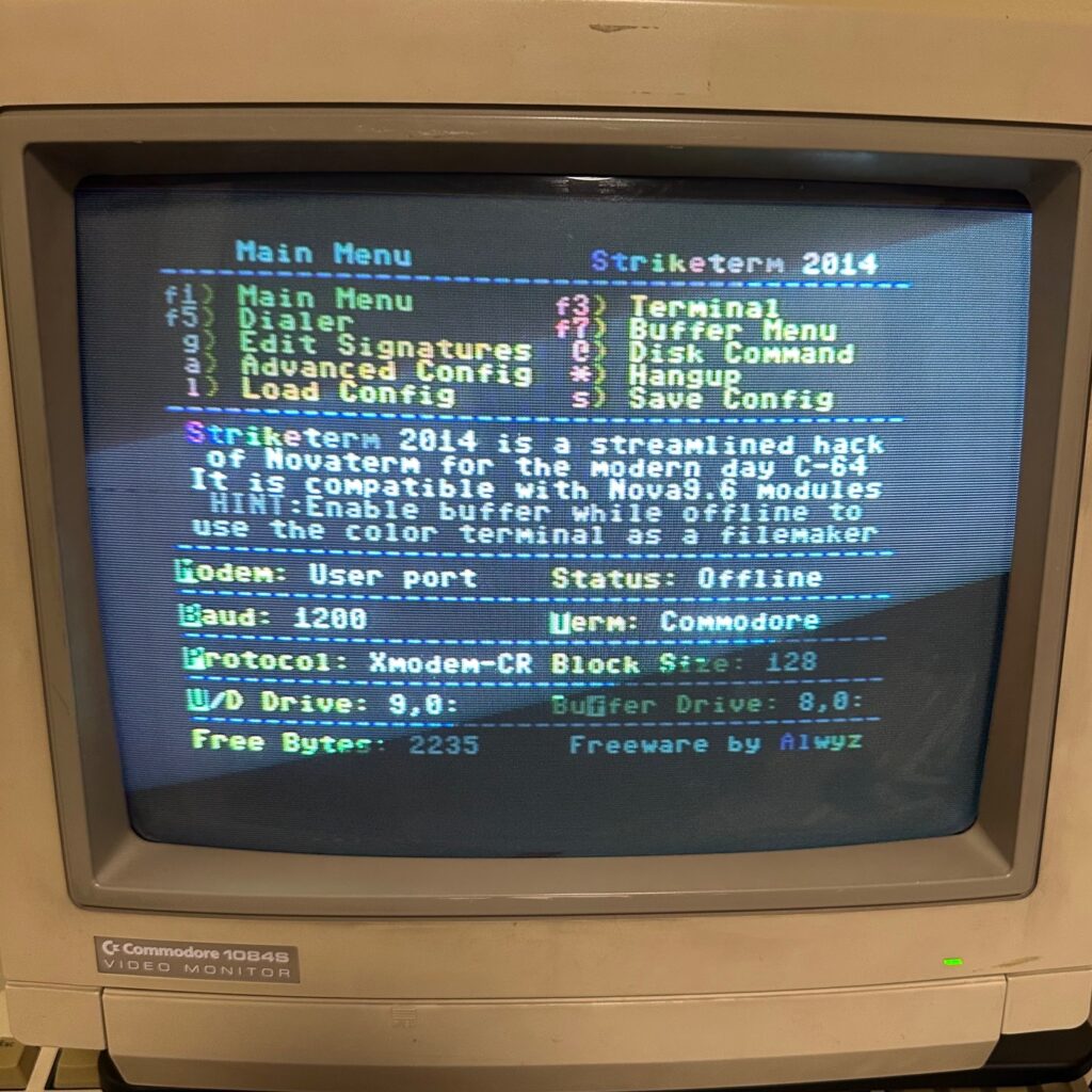
In the terminal program, set your modem / serial driver (such as User Port) and the baud rate to 1200.
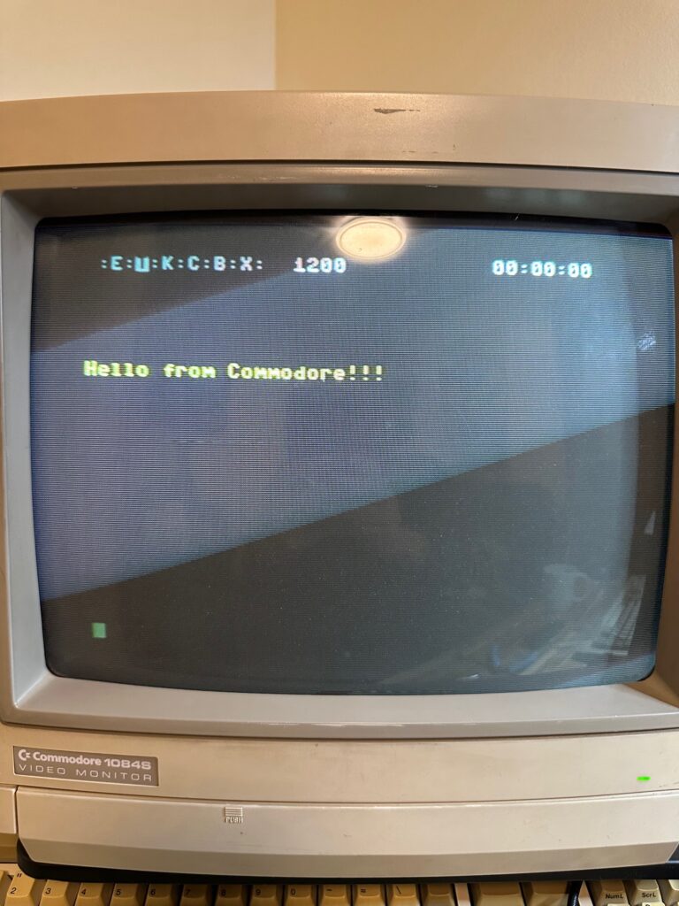
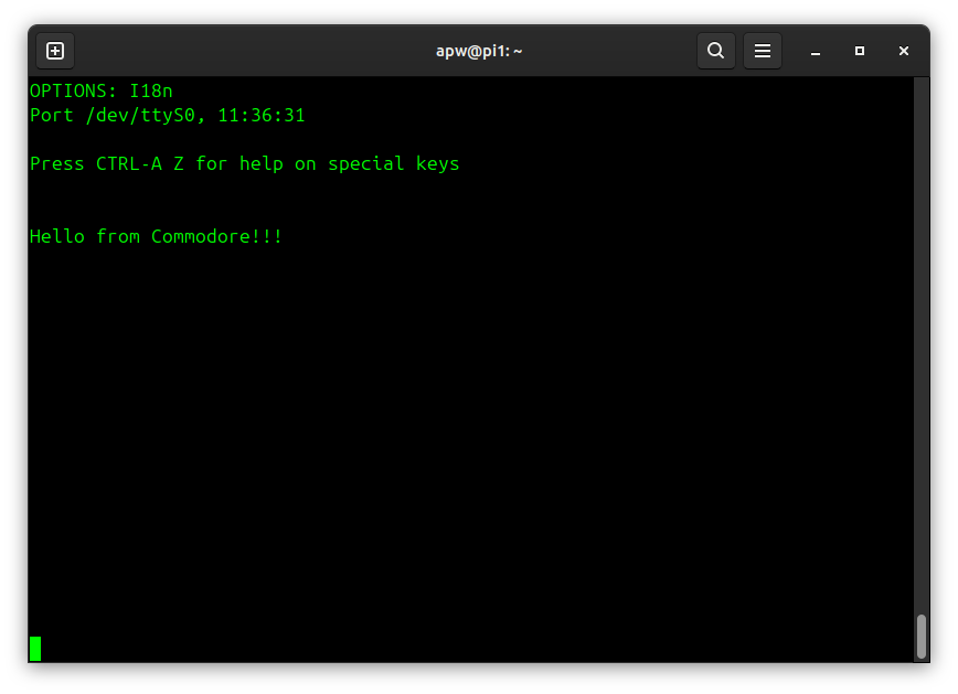
Now, enter the terminal on the C64 and type something. With any luck, you should see the text you just typed appear in the Minicom terminal on the Raspberry Pi.
Troubleshooting
If you see gibberish, double-check the baud rate, data bits, parity, and stop bit settings matches on both sides. In other words, both sides should be set to 1200 baud with 8N1 (8 data bits, no parity, 1 stop bit).
If you see nothing, try adding or removing a null-modem adapter to flip where pin 2 on the serial cable is connected.
If you need to enable Local Echo in the Commodore terminal to see your input and/or you see a gibberish character printed in the Commodore terminal after every character that you send, then the most likely fix is to set the Termination Resistor on the Pi-485 by switching that jumper setting on the HAT board.
Implementing a Modbus TCP Gateway
Modbus is a standard communication protocol used by industrial electronic devices and programmable logic controllers (PLCs) used in manufacturing and other industrial applications. Modbus supports communication to and from multiple devices connected to the same cable or network. For example, there can be a device that measures temperature and another device to measure humidity connected to the same cable, both communicating measurements to a single server. Modbus utilizes serial connections or TCP/IP networks. For our purposes as home experimenters and enthusiasts, we are going to use the Modbus TCP protocol to supply data to Ignition.
To connect the Commodore 64 to Ignition, we are going to build a Modbus TCP gateway server. We will implement this in Python using the PyModbus library. Our program will run on the Raspberry Pi, creating a Modbus TCP server that Ignition can use as a device data source. It will read any data sent from the Commodore 64 via the serial port and then write that data into Modbus holding registers that can be served to Ignition.
The key portion of the server code is in overriding the get_holding_registers method in a MyDataBank class, as seen in the excerpt below. The overridden method reads bytes from the serial port and then places them in holding registers in the data bank.
from pyModbusTCP.server import DataBank, ModbusServer

class MyDataBank(DataBank):
    """A custom ModbusServerDataBank for override get_holding_registers method."""

    def __init__(self, port):
        # turn off allocation of memory for standard modbus object types
        # only "holding registers" space will be replaced by
        # dynamic build values.
        self.serial_port = port
        super().__init__(virtual_mode=True)

    def get_holding_registers(self, address, number=1, srv_info=None):
        """Get virtual holding registers."""
        # populate virtual registers dict with bytes read from serial port

        rx = self.serial_port.read_data(3)
        if rx:
            print(f"Received: {rx.decode('utf-8')}") # Decode bytes to string
            if len(rx) == 1:
                v_regs_d = {0: rx[0], 1: 0, 2: 0}
            elif len(rx) == 2:
                v_regs_d = {0: rx[0], 1: rx[1], 2: 0}
            else:
                v_regs_d = {0: rx[0], 1: rx[1], 2: rx[2]}
        else:
            print("No data received or error occurred.")
            v_regs_d = {0: 0, 1: 0, 2: 0}

        # build a list of virtual regs to return to server data handler
        # return None if any of virtual registers is missing
        try:
            return [v_regs_d[a] for a in range(address, address+number)]
        except KeyError:
            return
In the main program loop when the Modbus server is created, the MyDataBank class is passed as the data_bank parameter.
serial_port = MySerialDevice(port=args.device, baudrate=args.baudrate)

srv = ModbusServer(host=args.host, port=args.port, data_bank=MyDataBank(serial_port))

srv.start()
The code for this Modbus TCP gateway server can be found on GitHub: https://github.com/awhitney42/modbus-server
When running the server, the serial device must be specified as the first argument. You can also specify additional parameters such as:
- -H : server hostname or IP address
- -p : server listen port (default: 502)
- -b : serial port baud rate (default: 1200)
- -t : serial port receive timeout (default: 1 second)
python server.py /dev/ttyS0 -H localhost -p 5020 -b 1200 &Adding Modbus Devices and Tags to Ignition
This section describes the process for connecting Ignition to your Modbus TCP gatway server running on the Raspberry Pi and acquiring and storing the data sent to Ignition. There are several steps required, so take your time and pay close attention to these instructions, especially when adding the OPC tags for the device connection.
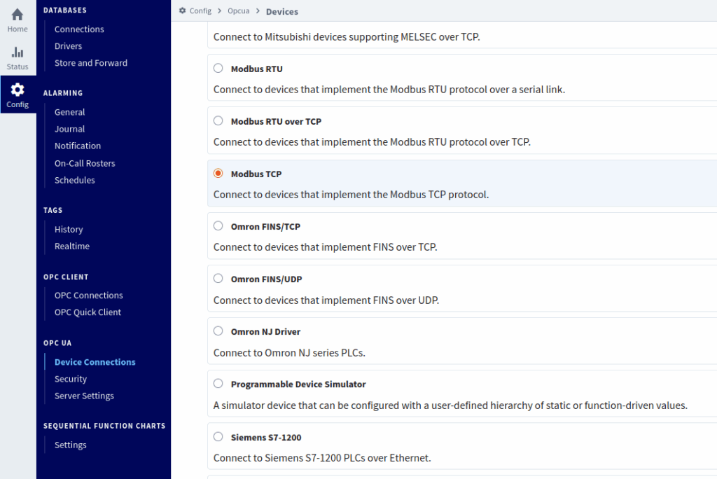
To connect Ignition to your Modbus TCP gateway server, you need to add a Device Connection in the Ignition Gateway. To add a device go to Config > OPC UA > Device Connections in the left menu. Select “Modbus TCP” for the device type and click “Next”.
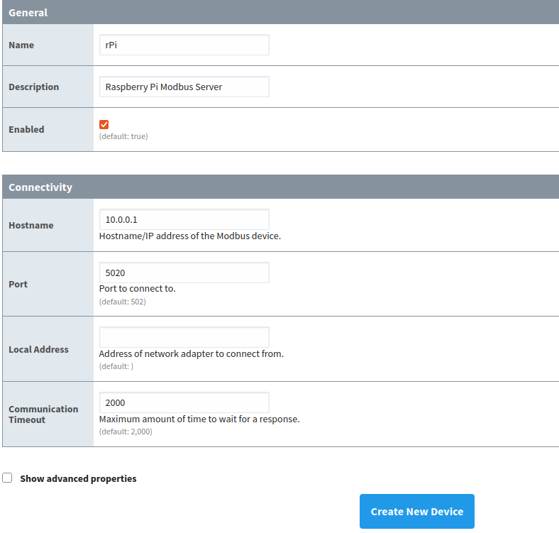
Enter a name and description for your device in the General section. Enter the IP address (or hostname) of your Raspberry Pi in the Hostname field and enter the Port number that your server is using to listen. I am using the non-standard port of 5020 in this example.
Make sure your Python server script is running on your Raspberry Pi.
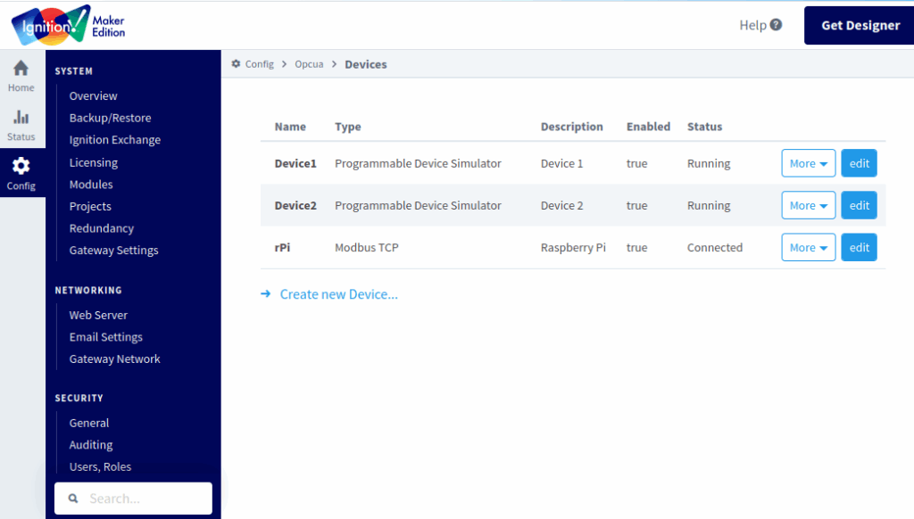
If Ignition is able to successfully connect to your Modbus TCP gateway server on the Raspberry Pi, you will see the status of “Connected” in the list of OPC UA Devices in the Ignition gateway!
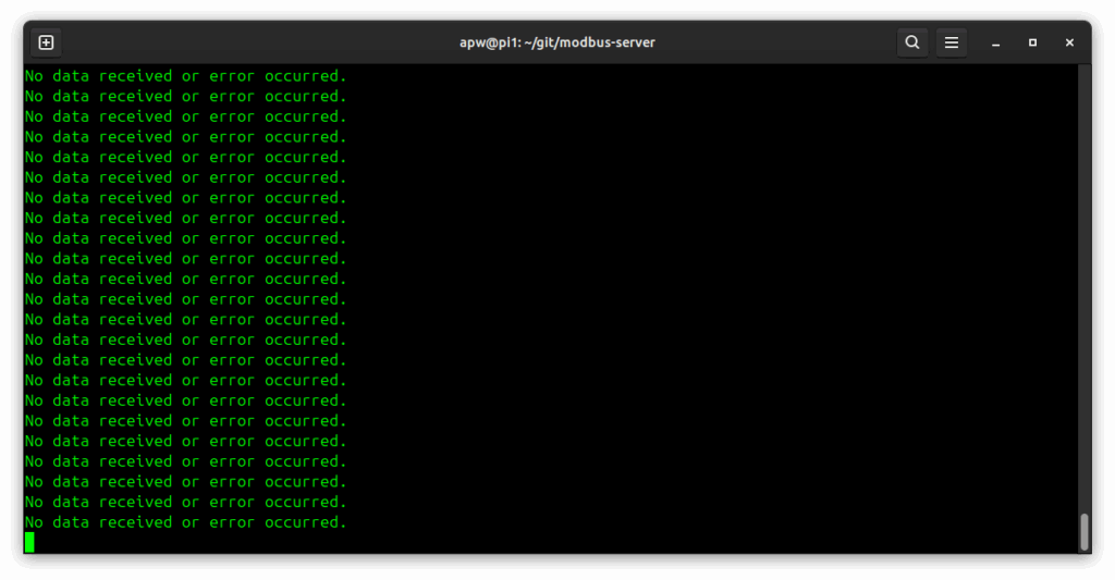
You should also start to see some debug messages being printed by the Python program: “No data received or error occurred.” This is normal debug output indicating that the server script has an active client connection from Ignition.
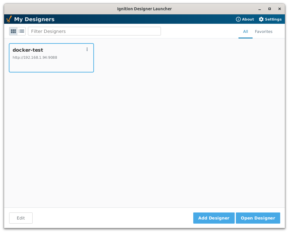
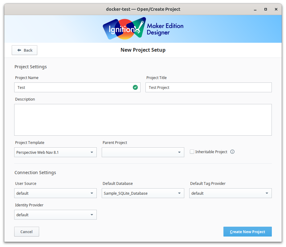
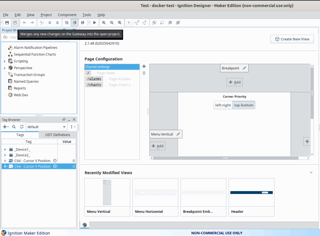
Next, open up Ignition Designer, connect to your gateway, and create a new “Test” project.
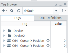
Designer has a Tags Browser that lets us view and create OPC tags on the gateway. We are going to create two new tags:
- C64 – Cursor X Position
- C64 – Cursor Y Position
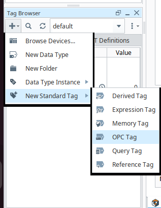
To create these tags, click the Add (+ sign) menu for the Tag Browser. Select “New Standard Tag” > “OPC Tag”.

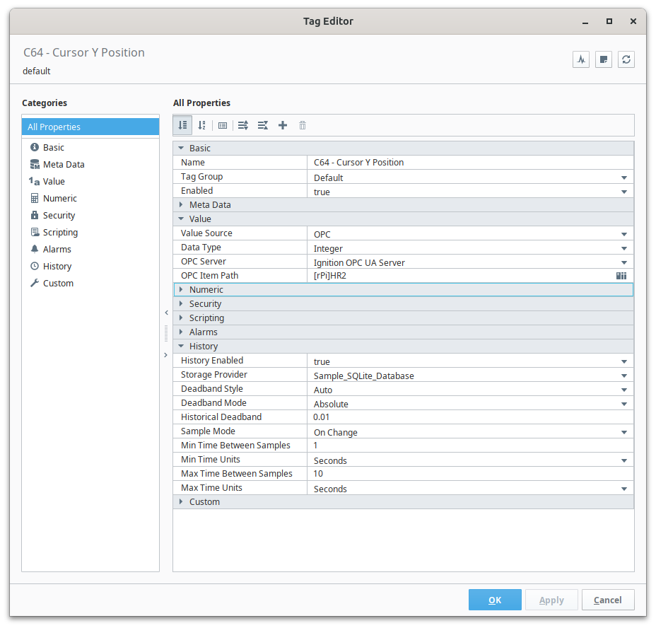
For the new tag, enter the following configuration:
- Basic
- Name: C64 – Cursor X Position
- Value
- Value Source: OPC
- Data Type: Integer
- OPC Server: Ignition OPC UA Server
- OPC Item Path: [rPi]HR1
- History
- History Enabled: true
- Storage Provider: Sample_SQLite_Database
- Sample Mode: On Change
- Min Time Between Samples: 1
- Min Time Unit: Seconds
- Max Time Between Samples: 10
- Max Time Unit: Seconds
I have highlighted in bold some the most important tag settings.
The Data Type for this tag should be set to Integer, as we intend to send integer values from the Commodore 64.
The most important setting is the OPC Item Path. The value of “[rPi]HR1” specifies the following:
- Device Connection: rPi – This specifies the name of the OPC Device Connection
- Holding Register Address: HR1 – This specifies Holding Register 1 for the value
In the History settings we want to set History Enabled to “true”. When set, Ignition will begin to store a historical record of all of the values acquired for this tag in the default Storage Provider of “Sample_SQLite_Database“. We want to set the Sample Mode to “On Change” to only store a new record if the value changes. Finally, we want Ignition to sample this tag a minimum of “Every 1 Second” to check for changes in the tag’s value.
Click OK to save the tag.
Next, create another new OPC Tag called “C64 – Cursor Y Position“. Enter the same settings for this tag, with one important difference:
- OPC Item Path: [rPi]HR2
This specifies Holding Register 2 on the rPi Device for the value source for this tag.
Click the Save and Update Project (Merge) in the Designer window’s File menu or ribbon, to make sure everything is saved and uploaded to the Ignition gateway server.
Now, got back to Ignition in your web browser and Run your Test Project!
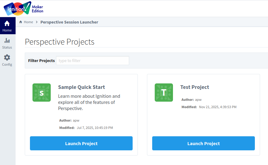
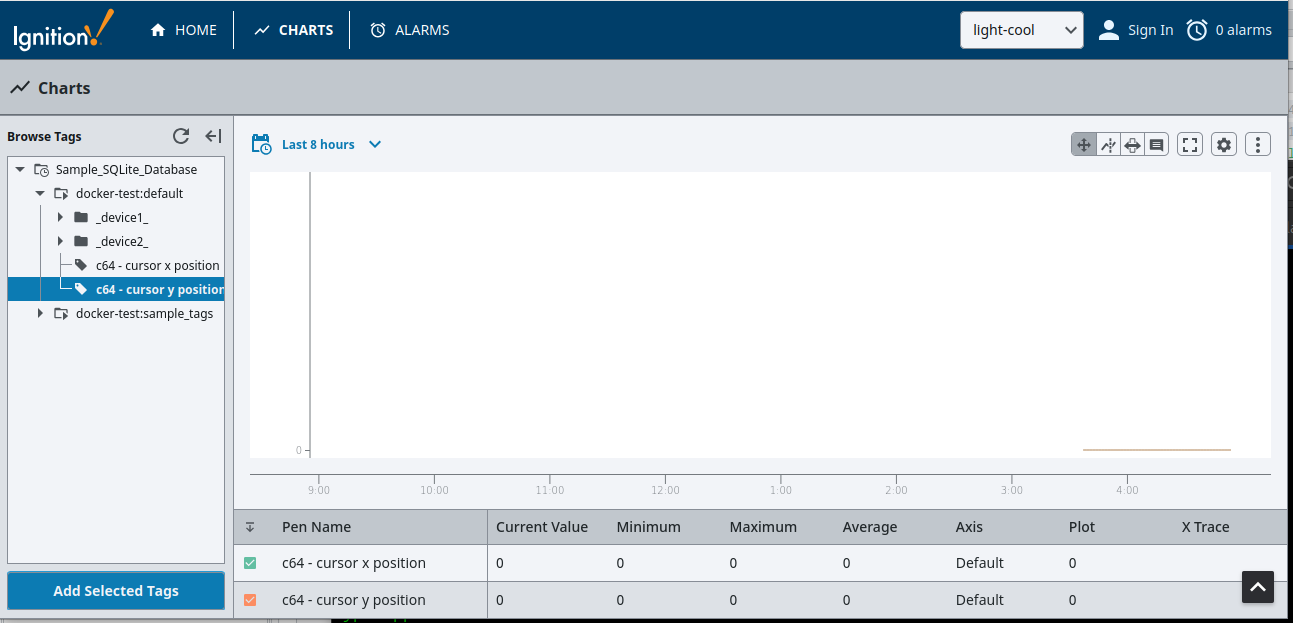
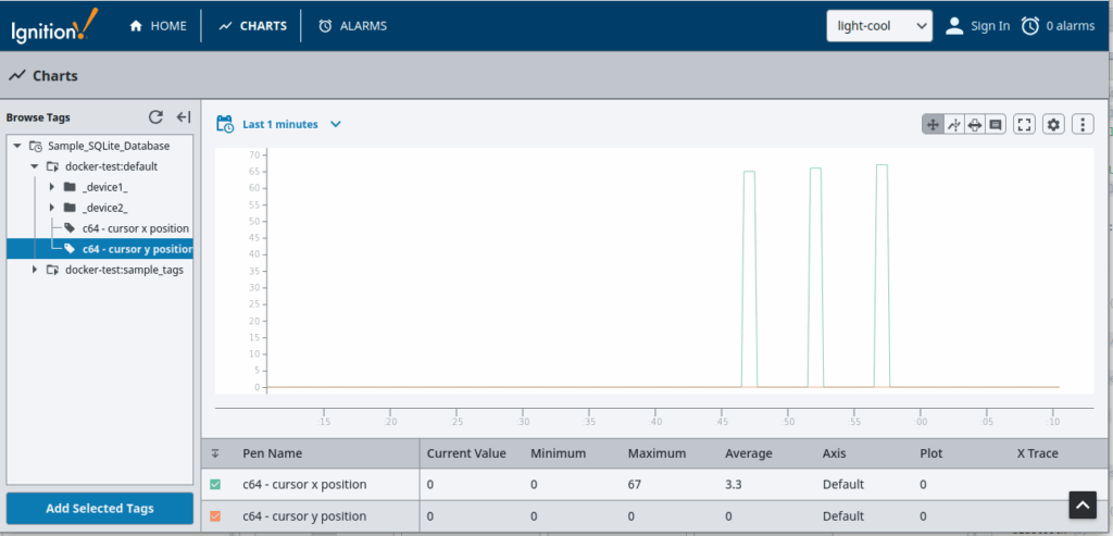
When you run your Perspective “Test Project” you will see a mostly empty home page. Click on the Charts item in the upper menu.
On the Charts page, open the Tag Browser and navigate to Sample_SQLite_Database > default. Add your two C64 tags! You should now see those tags listed at the bottom of the chart, showing statistics on the history of their values. Set the chart’s time range to show the “Last 1 Minute”.
This is the moment of truth. Make sure that your Commodore 64 is still connected to your Raspberry Pi via the serial cable, the Python server script is still running, and that Ignition shows the “rPi” device status as “Connected”.
Go to your Commodore 64 terminal program and type:
a
Wait five seconds and then type:
b
Wait five seconds again and then type:
c
If all is working, you should see three data points having been captured by Ignition! This shows a stair step of the values that were sent in Holding Register 1 as you typed “a” (ASCII 65), “b” (ASCII 66) and “c” (ASCII 67).
Commodore 64 Data Acquisition
Now that we have connected our Commodore 64 to Ignition, let’s go one step further and create some code that runs in the background on the C64, sending data periodically to Ignition.
When a Commodore 64 is powered on, it executes a reset sequence that sets all of the hardware and software in the computer to a starting state that is coded into the computer’s ROM chips. At the end of this reset sequence, the interrupt vector address at $0314 – $0315 will be contain the memory address of $ea31 located in kernal ROM, where the IRQ interrupt handler routine begins.
On a Commodore 64, an IRQ interrupt signal strikes sixty times a second. This executes the interrupt handler routine, which performs many critical tasks for the computer. It updates the clock, checks the RUN/STOP key, gives service to the cassette motors, flashes the cursor, and handles keyboard input.
One of the amazing things about the Commodore 64 is that it give you the power to modify the system at a fundamental level. While it’s not a great idea to replace the default interrupt handler (at the very least the keyboard would go dead), it is perfectly acceptable to extend the interrupt handler to do additional tasks! To send data periodically in the background, we are going to do just that.
The modbus-server repository in GitHub contains some assembly code for a custom interrupt handler routine that can be loaded in Turbo Macro Pro and assembled into memory. This is located in the “examples” directory in the project: C64 Interrupt Handler Routine
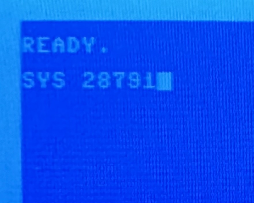
This routine assembles into memory address $7000. It can be installed by executing $7077 (28791 in decimal).
SYS 28791When this routine is installed, it takes the current interrupt vector value stored at address at $0314 – $0315 and writes it to zero-page memory location $03a0 – $03a1. It then modifies the value stored in the interrupt vector address to point to this routine at memory address $7000. From that point on, every IRQ sixty times per second will execute our code at $7000.
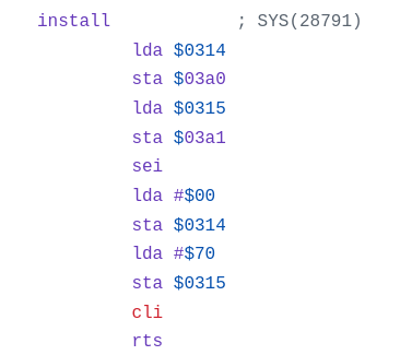
In this way we are able to run our own code in the background alongside the main system interrupt handler.
For our custom code, we are going to send the horizontal (X) and vertical (Y) position of the Commodore 64 screen cursor to the serial port approximately every 4 seconds (so as to not overload the slow speed of the 1200 baud serial connection).
The first three lines at the START label allow us to skip our routine unless the value in the system’s jiffy clock address at $00a2 is zero. This happens about every 4 seconds.
start    lda $a2
         cmp #$00
         bne skipsend
If the value is zero, then we continue to run our routine. Most of the code shown here involves opening the serial port as shown by the comments.
         lda #$00  ; no filename
         ldx #$00
         ldy #$00
         jsr $ffbd ; setnam

         lda #$05 ; logical file #
         ldx #$02 ; 2 = rs-232 device
         ldy #$00 ; no cmd
         jsr $ffba ; setlfs

         ; c64 rs-232 registers

         lda #$08 ; 1200 baud,8 bits
         sta $0293 ; serial control reg

         lda #$00 ; fullduplex,no parity
         sta $0294 ; serial command reg

         ; open file

         jsr $ffc0 ; open file

         ldx #$05  ; logical file #
         jsr $ffc9 ; chkout
         bcs error
Finally, we get to send some data! The cursor’s X position is stored in address $00d3 and the Y position is stored in address $00d6. We send these two byte values to the serial port by calling subroutine $ffd2, and then send a final #$00 byte.
         lda $d3
         jsr $ffd2
         lda $d6
         jsr $ffd2
         lda #$00
         jsr $ffd2 ; send final kludge
         jsr wait
         jmp exit
At the very end of our custom interrupt handler, we perform a JMP to the address stored in $03a0 to continue running the main system interrupt handler and all of its essential tasks, after our custom code is done.
jmp ($03a0)If needed, the routine can be uninstalled by executing address $7090 (28816 in decimal), which reverts the system back to using the default interrupt handler in kernal ROM.
SYS 28816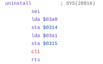
Data Flow In Action
If you installed the interrupt handler by executing $7077 (28791 in decimal), then it is already running and sending data!
Look at your chart in Ignition and verify that you are receiving data. If your Commodore 64 screen cursor is at the home position (0, 0) make sure to move it around the screen.
Move the cursor to different screen positions, and you will see the data sent to Ignition every 4 seconds showing the current X and Y position of the screen cursor on the Commodore 64!
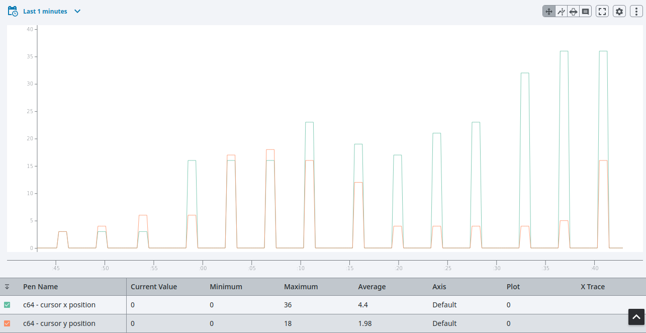
We did it! We connected our Commodore 64 to Ignition to accomplish data acquisition from the most important device in your home facility. Revel in the magic.